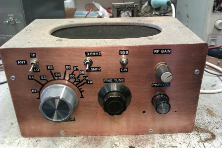
Here is a simple direct conversion receiver for 80m ( also known as a DC RX ). The receiver covers 3.51 MHz - 3.60 MHz and 3.64MHz - 3.71 MHZ thus CW and Phone portions of the band are usable, this is acheived by using a VXO with two switchable ceramic resonators. Stability of the VXO is very good. The set has two filter bandwidth settings, one for SSB and the other for CW. Sensitivity of the receiver is good ( for a DC RX ), signals in the 3uV region are easily copied.
A look at the circuit diagram will show how straight forward this set is. The aerial signal first passes through a 2K2 pot which is used as a crude but effective RF attenuator, this is necessary if strong adjacent signals are present. A single pole bandpass filter follows the attenuator, a switch is used for hi / lo impedance aerials. In the lo impedance position the aerial signal is coupled to the lo impedance winding on L1. In the hi position the aerial is coupled to the hi impedance input of the bandpass filter. This can be useful for a end fed random wire aerial as its impedance can vary greatly depending on its length, you can omit this feature if the set is being fed from a 50 Ohm aerial.
A MOSFET RF preamp ( Tr1 ) provides a small amount of gain before the signal passes through to the mixer D1, D2. For Tr1, most dual gate mosfets should be ok. The wanted AF mixing product ( i.e the demodulated audio signal ) leaves the mixer via RFC1, this allows audio to pass but not RF. The audio source impedance from the mixer is very low ( less than 200 Ohms ) so a grounded base audio preamplifier Tr2 is used after the mixer, this gives a very good impedance match to the mixer outputallowing good power transfer from the mixer to the preamp. Two active low pass filter stages ( Tr3, Tr4 ) follow the audio preamp, these provideall of the selectivity for the set, no voltage gain is produced by these two stages.A two way switch is used to select audio from the first or both active filters thus giving two bandwith options, SSB from the first filter or CW from both filters cascaded. The second filter has a slighly lower cut off frequency than the first and does result in slightly lower volume but it is worth it for the much narrower bandwidth.
Another preamplifier Tr5, follows the filter stages via a volume control. Output from the preamp is then raised to speaker level by IC1, a LM386.
Once built the only setting up required is to peak L1 for maximum signal strength at 3.5MHz and to peak CT for maximum signal strength at 3.6MHz.
The set uses a VXO for the local oscillator, two ceramic resonators are used, a 3.58 MHz and a 3.68 MHz both of these are available from the G- QRP club as is the polycon tunning capacitor and pad cutting tool for the circuit board. A simple colpits oscillator is employed followed by a buffer. A vaicap diode provides fine tuning of the VXO as no reduction gearing is used with the tunning capacitor. In use, the set performs well and is a handy item to have around the shack. Construction is not difficult but a logical layout should be used as there is a lot of gain present in this circuit, keep inputs away from outputs etc. and do not skimp on any of the supply rail decoupling capacitors otherwise instability will occur. Use a screened lead for the speaker inter- connecting wire.
Barry Zarucki M0DGQ
HOME